
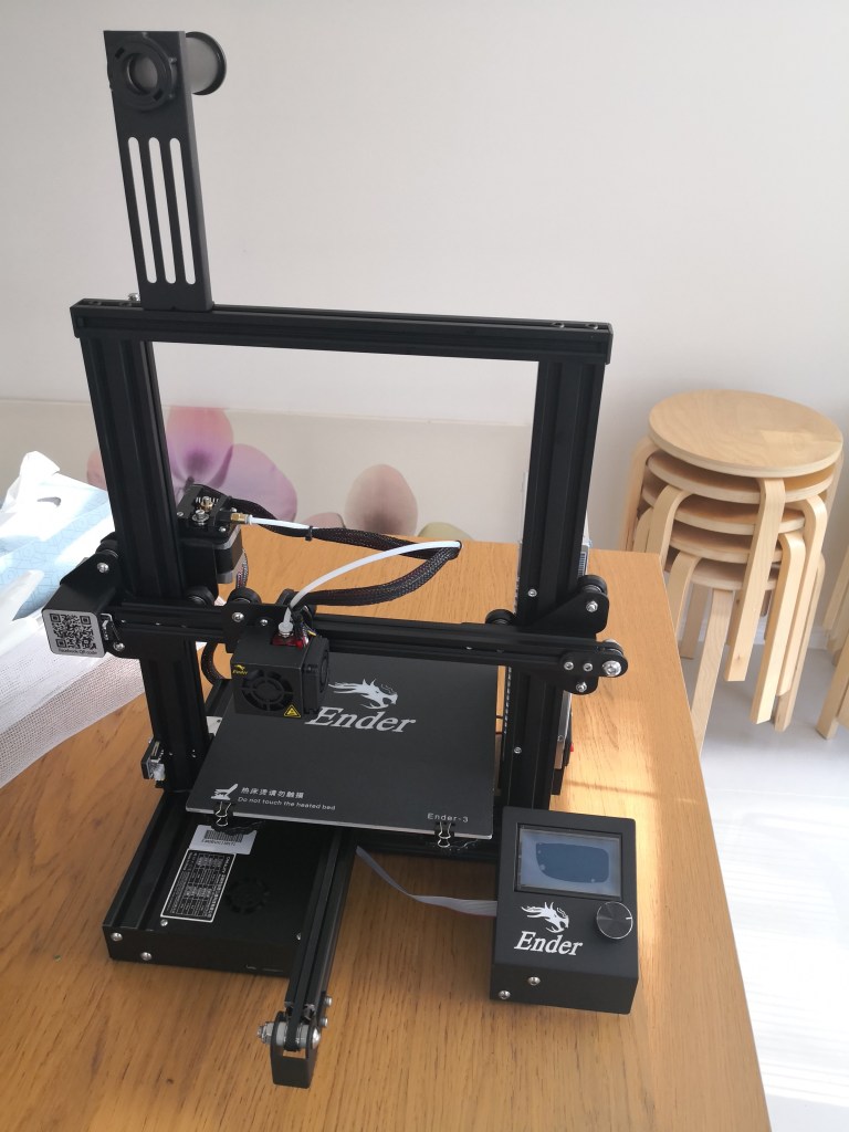
The Ender 3 v1 was my very first 3d printer purchased right before the 2018 Xmas. For the last four years, it has served me well and taught me quite a few things about 3d modelling and mechanics. Although it’s one of the most popular printers on the market, it does not mean it a perfect one. In fact, it requires a lot of tuning and modifications. Over the last four years, I’ve done quite a few small incremental mods. However, most of the mods were from the other’s designs on Thingiverse and some does not feel very satisfactory to me. Now that I have got my second printer in service and also feel more confident on 3d modelling. It’s time to do a completely redesign and rebuild of my good old Ender 3.
This note will record the progress of this rebuild project and will hopefully remind myself some useful details. I’ll keep updating this note until I get a much more reliable and better performance Ender 3 Ultra.
One of the top priority mod
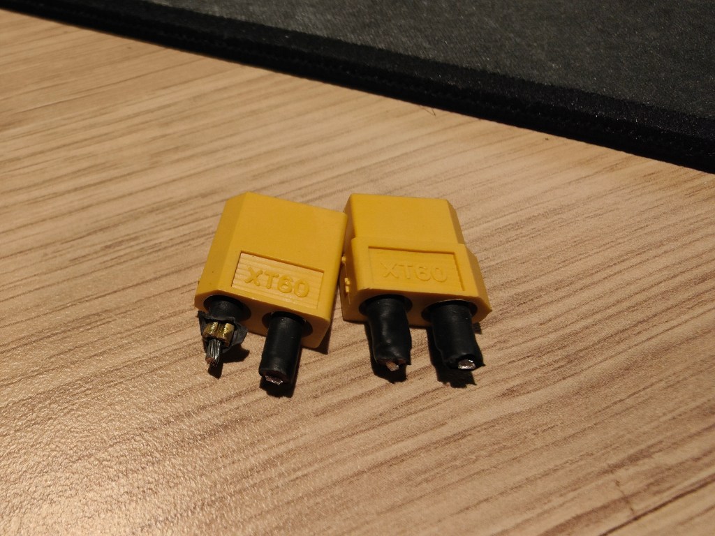
Check and replace these XT60 connectors. They do feel very hot during printing. Very high risk fire hazard!
Maker’s Muse has covered this in very good detail https://youtu.be/4yDp9frWkcg.
Square the frame
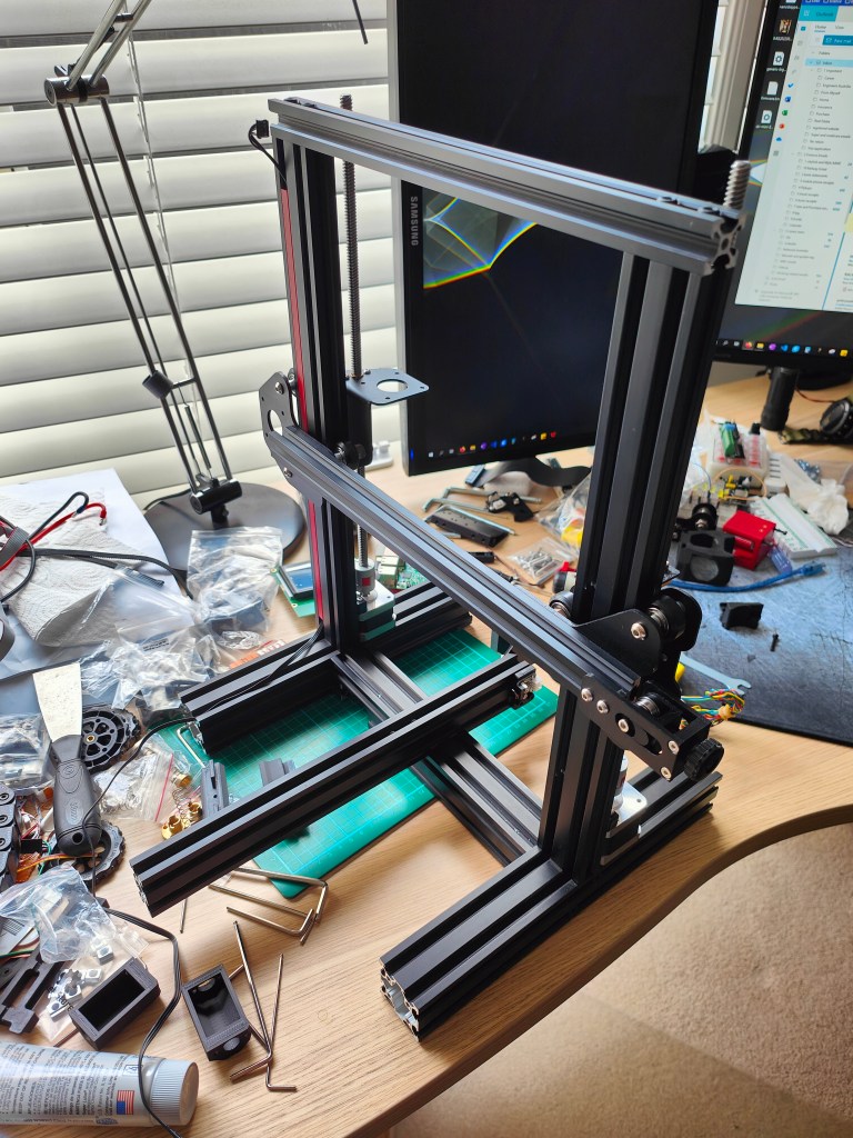
Almost everything was firstly removed from the frame (including the gantry). The two Z-axis 2040 Al-extrusion are not quite parallel to each other in the original assembly (wider on the top and slightly narrower at the bottom). A very thing shim, about 0.6mm in thickness, was designed and added in between the based 4040 Al-extrusions (available from Printable page https://www.printables.com/model/452213-4040-aluminium-extrusion-shimspacer). After very careful checking, all three axes were properly squared.
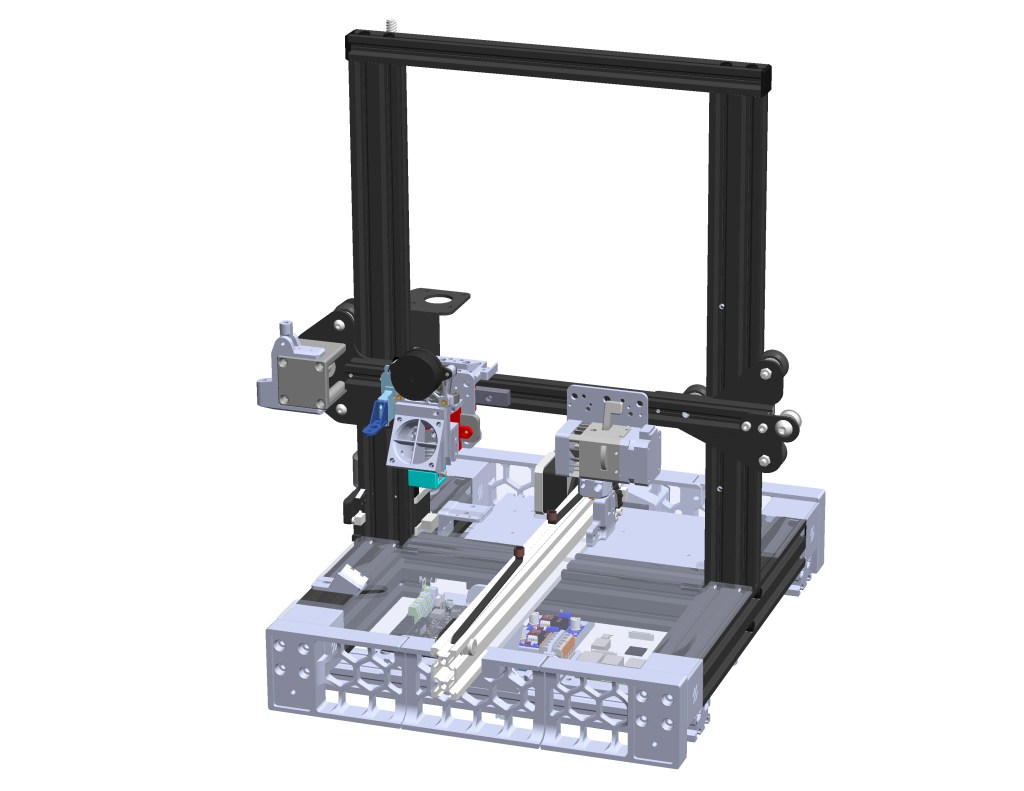
Modification plan
A very rough plan for this project
- Relocate all electronics to the base of the printer and build a enclosure on the top similar to the Voron switchwire design.
- Add dual Z-axis drive.
- Add linear rail to X and Y axes.
- Properly mount the Printermods Xchange tool change system.
- Move Y axis Al-extrusion forward to accommodate the tool head change
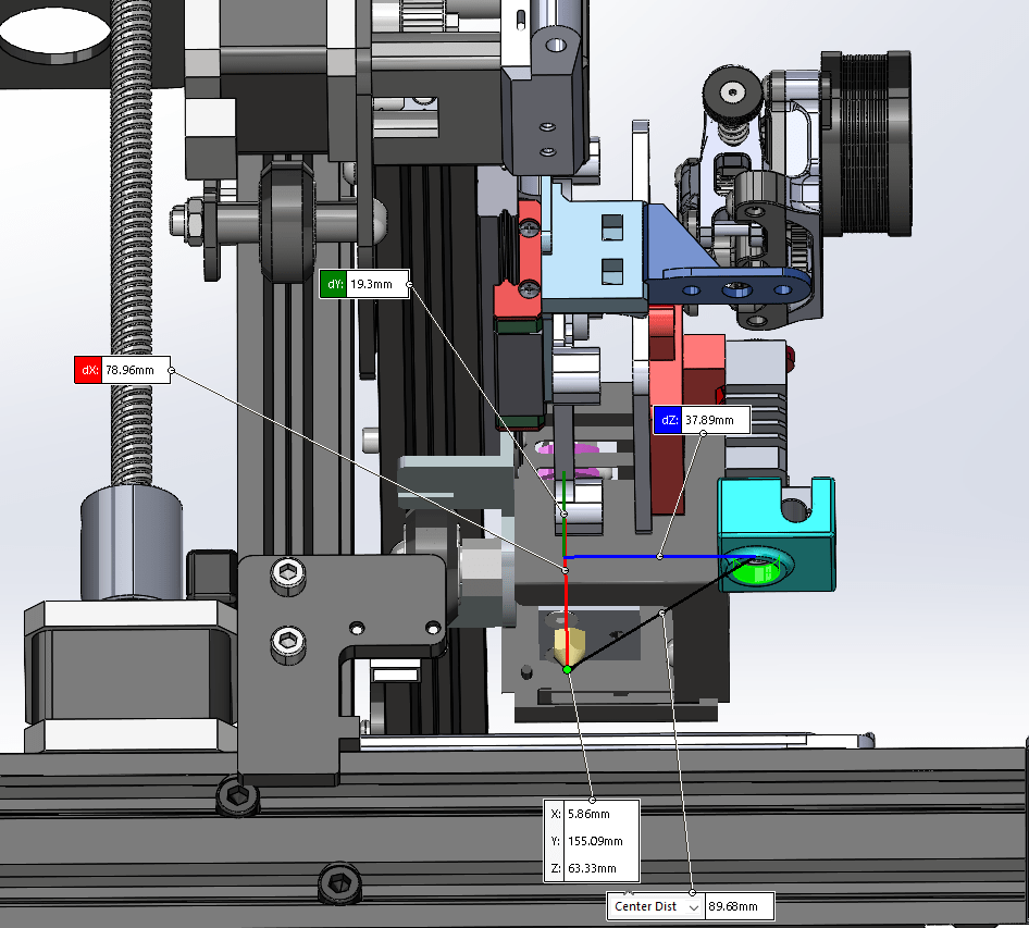
All the detailed designs will be refined during rebuild, but here is my current progress in CAD. By the time of writing this note, Printermods company does not seem to operate anymore (No support response according to facebook group communications). Therefore, it is recommend to choose an alternative product if tool changing system is preferred.
Structural modifications
Before moving to the installations of new parts, a few structural mods have to be made due to a few reasons:
- Adding Printermods xchange toolhead changing system will bring the nozzle forward by about 3-5mm (Herome Gen5 with microswiss all metal used in the image below).
- Adding y-axis linear rail adapter limits the movable range of printing bed. After adding y-axis linear rail, the bed movable range is pushed backwards.
- Shifting y beam forward to compensate the first two issues would make the y beam more like a cantilever beam. More support would be needed to improve structural stability.
- To move all electronics part to the bottom, there needs extra space to accommodate even if a slim Meanwell PSU is used.

Therefore, two extra 2040 beams were added to the bottom to create more clearance for electronics and improve y-axis stability with a support part.


Leave a comment